
-
-
Products

-
Company products

-
-
-
-
-


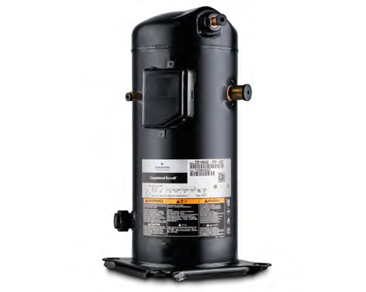
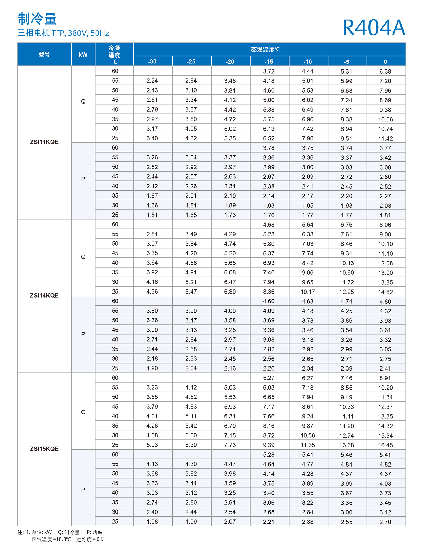
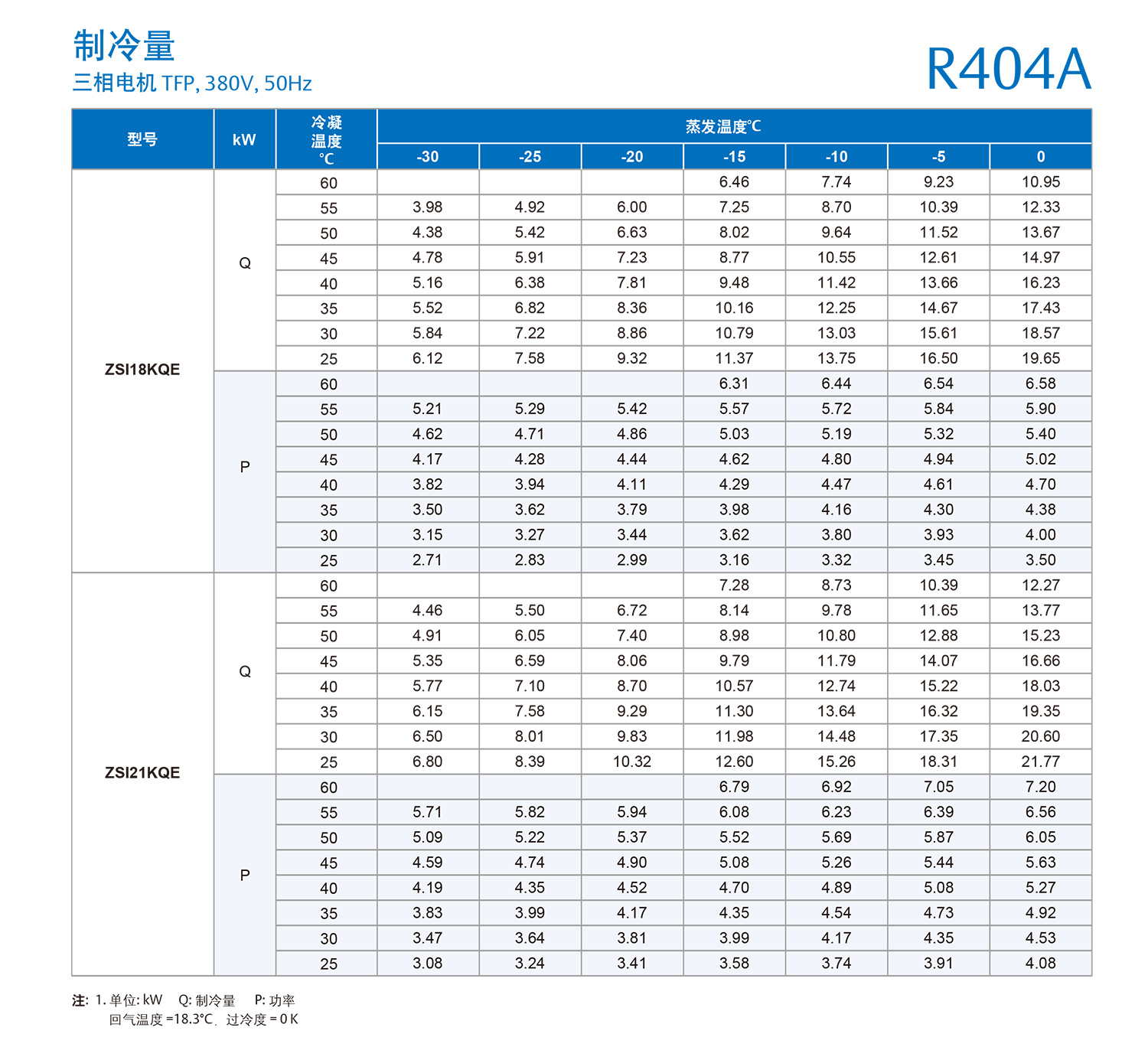
Copeland Scroll ZSI Series Frozen Compressor
Key words:
Classification:
Product Description
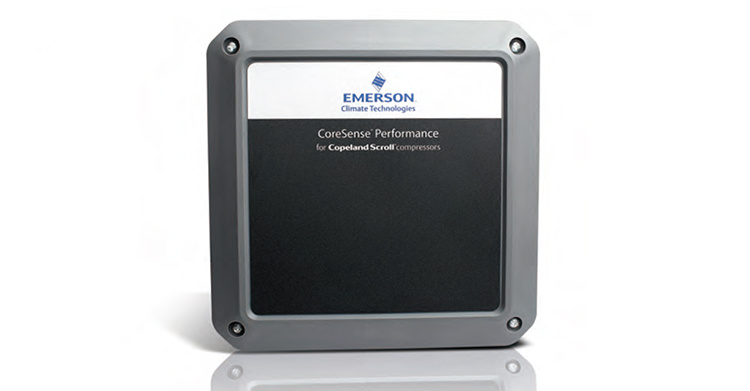
ZSI and CoreSense™Diagnostic Module
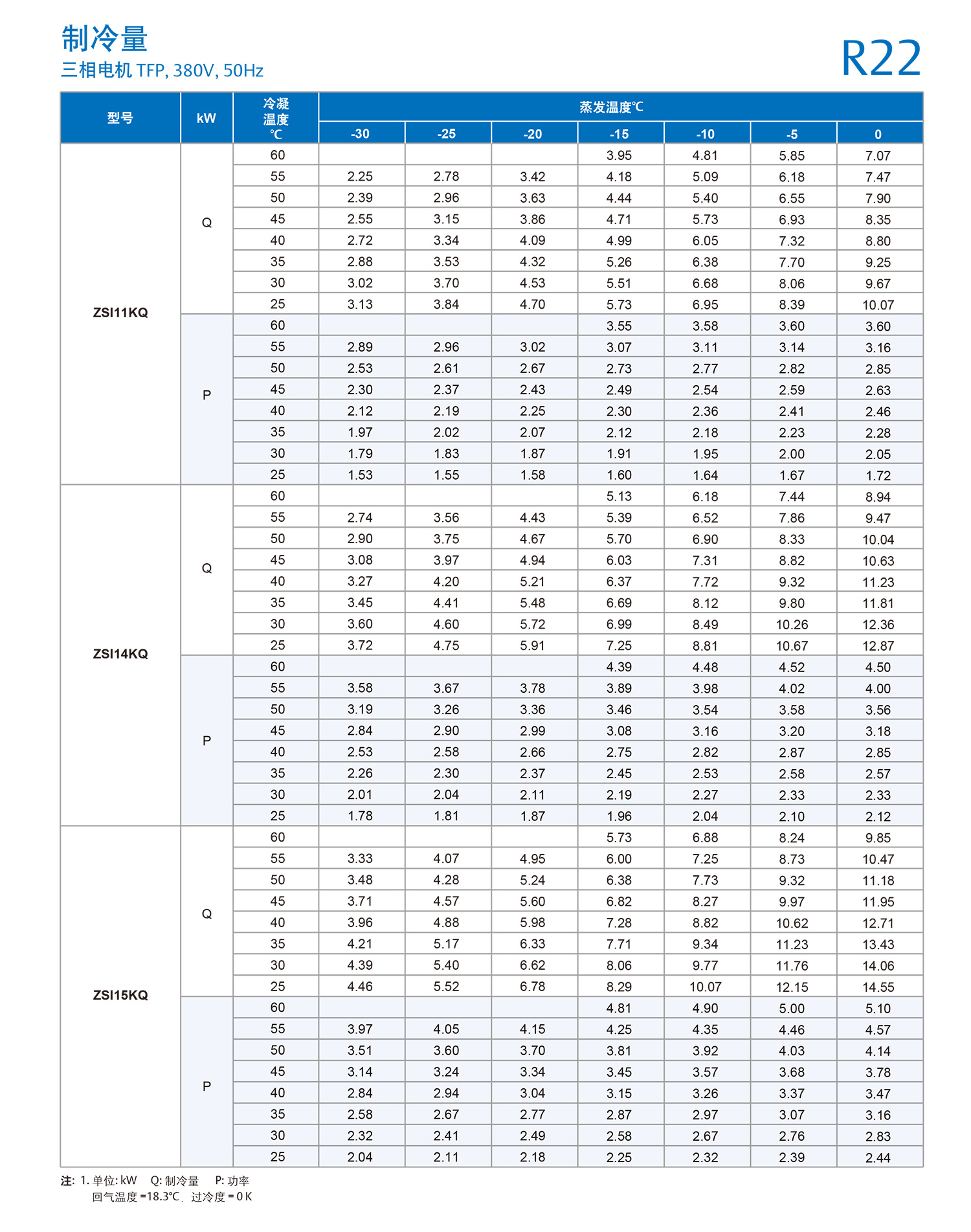
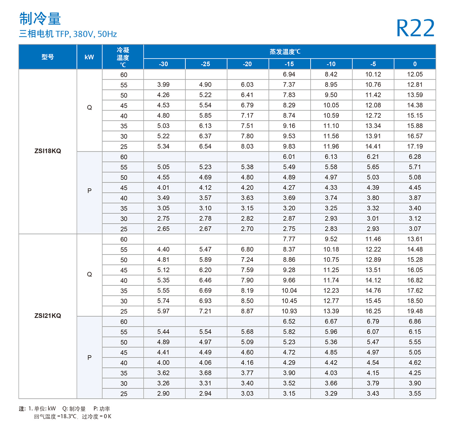
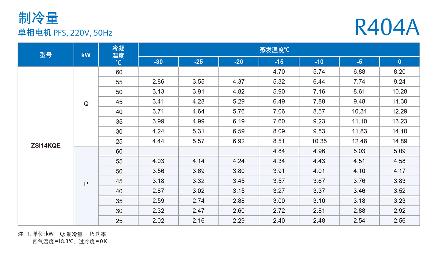
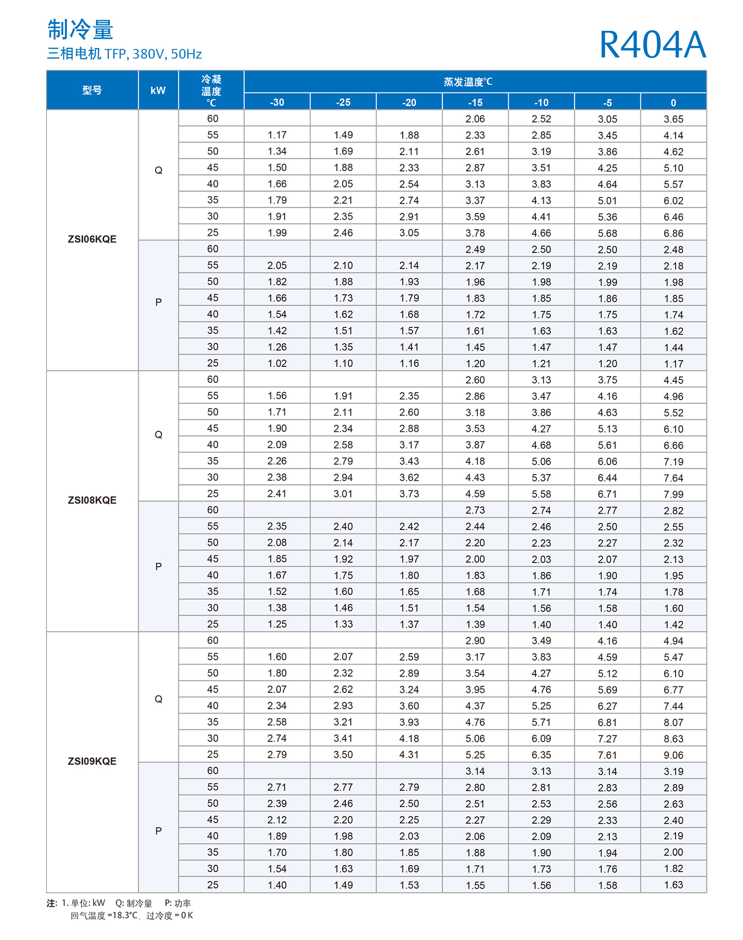
ZSI Scroll Compressor Product Information
Motor horsepower: 2-7.5 HP
Operating range: medium temperature and low temperature operation
Refrigerant: R22,R404A
The main advantages of ZSI scroll compressors
Scroll compressors for higher energy efficiency and reliability
Compared with piston compressors, scroll has a higher energy efficiency ratio. Based on different models, each scroll compressor saves 10% - 30% of electric energy or 600-3000RMB electricity cost per year.
• Reduced moving parts compared to traditional piston compressors, resulting in higher reliability
• Patented two-way flexible design, can make the scroll along the axial and radial separation, liquid and debris through the scroll without damaging the compressor
Scroll compressor runs smoothly
• Continuous compression process, less vibration, more quiet operation
• No complex internal suction and exhaust valve design, quiet operation, more reliable
Wide range operation
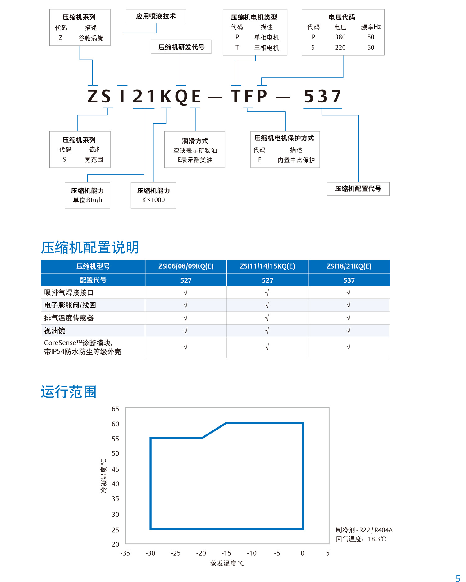
• Low to medium temperature applications, covering -30°C to 0°C evaporation temperature
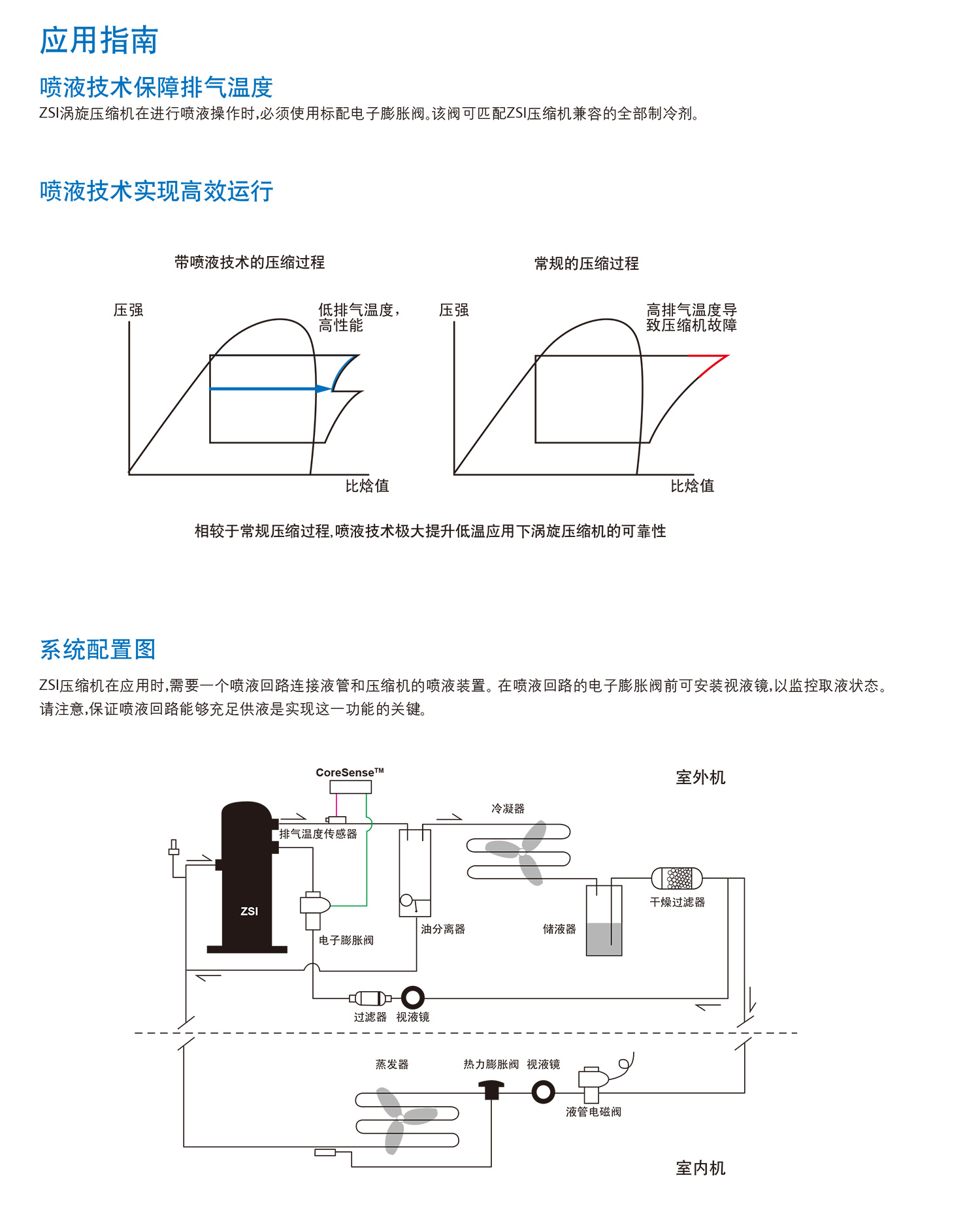
• CoreSense™Control liquid spray technology to improve the reliability of operation under low temperature conditions
• Wider operating range reduces inventory requirements
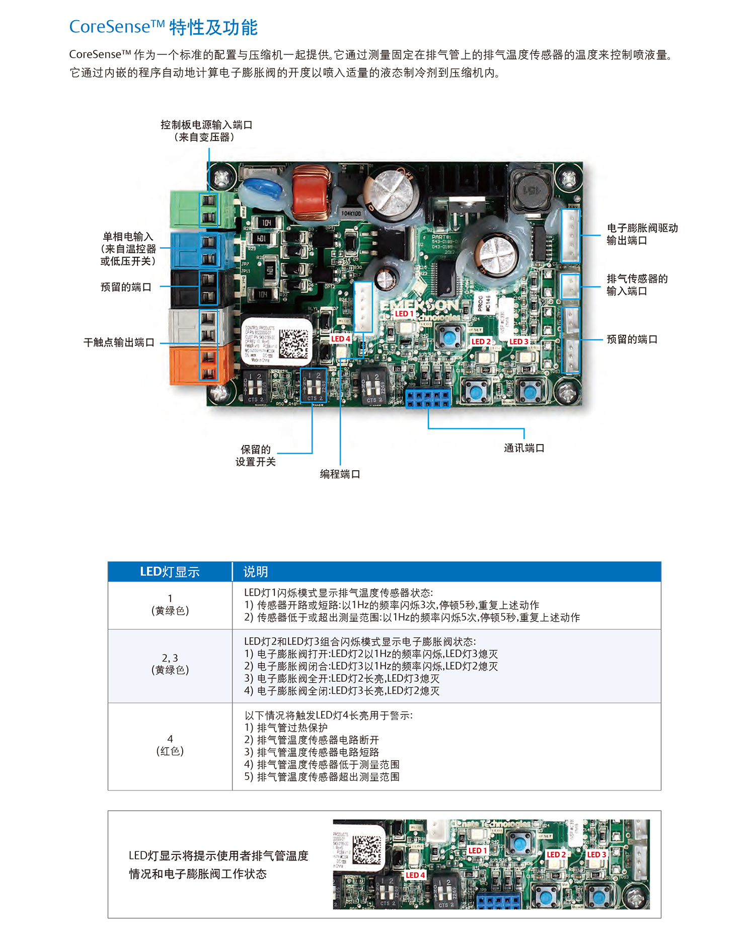
CoreSense™Diagnostic Module
ZSI scroll compressor utilization CoreSense™Diagnostic system for controlling liquid injection by measuring exhaust gas temperature. This technology not only expands the operating range of the compressor, but also ensures its reliability. CoreSense™The control board prompts the user of the sensor status and the operation of the electronic expansion valve through the LED light signal. Through this "smart compressor" strategy, Emerson aims to provide customers with better compressor protection, using exhaust temperature and electronic expansion valve monitoring to reduce the possibility of failure, and bring higher value and benefits to users.
• Through CoreSense™Controlled liquid injection technology avoids compressor failure due to high discharge temperature
• Precise control of spray volume by monitoring exhaust pipe temperature
• LED lights show the operating status of exhaust pipe temperature sensor and electronic expansion valve to help customers determine the cause of the fault more quickly and accurately
Naming Rules
Gas-liquid separator
The Copeland Flexible Scroll has the inherent ability to "tolerate" liquid refrigerant during occasional liquid return operation and liquid start-up, and the system may not need to use a gas-liquid separator.
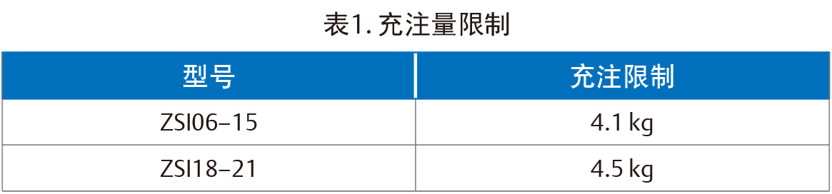
For a single compressor system, a gas/liquid separator is required when the refrigerant charge of the system exceeds the limits in Table 1. When the system handles defrosting operation or excessive operating conditions, the compressor may be affected by uncontrollable liquid return for a long time. Unless the suction header has sufficient capacity to prevent liquid from migrating into the compressor, a gas-liquid separator is required.
Note: when the gas-liquid separator is used, the mesh number of the oil return hole filter screen shall not be higher than 30 mesh.
superheat control
In order to ensure that the liquid refrigerant will not return to the compressor when the compressor is running, it is necessary to ensure that the compressor return port has a certain degree of superheat. Emerson recommends that the return gas superheat be not less than 20℉(11K) to ensure that the compressor is not affected by return liquid. The measurement position is 6 inches (152mm) from the compressor return port.
Another way to determine whether the compressor is liquid return is to accurately measure the temperature difference between the compressor oil tank and the return pipe. For long-term operation, we recommend that this temperature difference is not less than 50 °F (27K). When measuring the temperature of the oil tank, please place the thermocouple in the center of the bottom of the compressor body (not on the side), and keep warm to avoid environmental effects.
For rapid system changes, such as defrosting or frosting, this temperature difference may decrease rapidly in a short time. When the sump superheat is less than the recommend minimum of 50℉(27K), we recommend that the duration should not exceed 2 minutes, and the sump superheat should not be less than 25℉(14K).
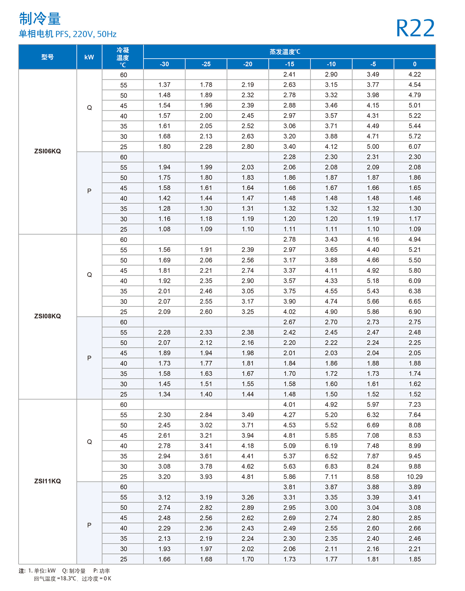
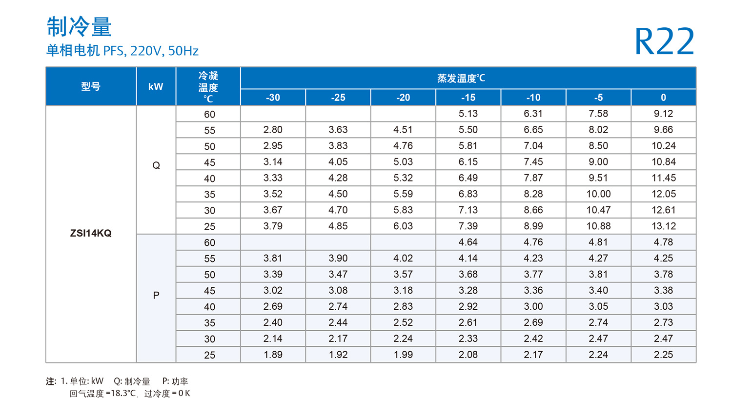
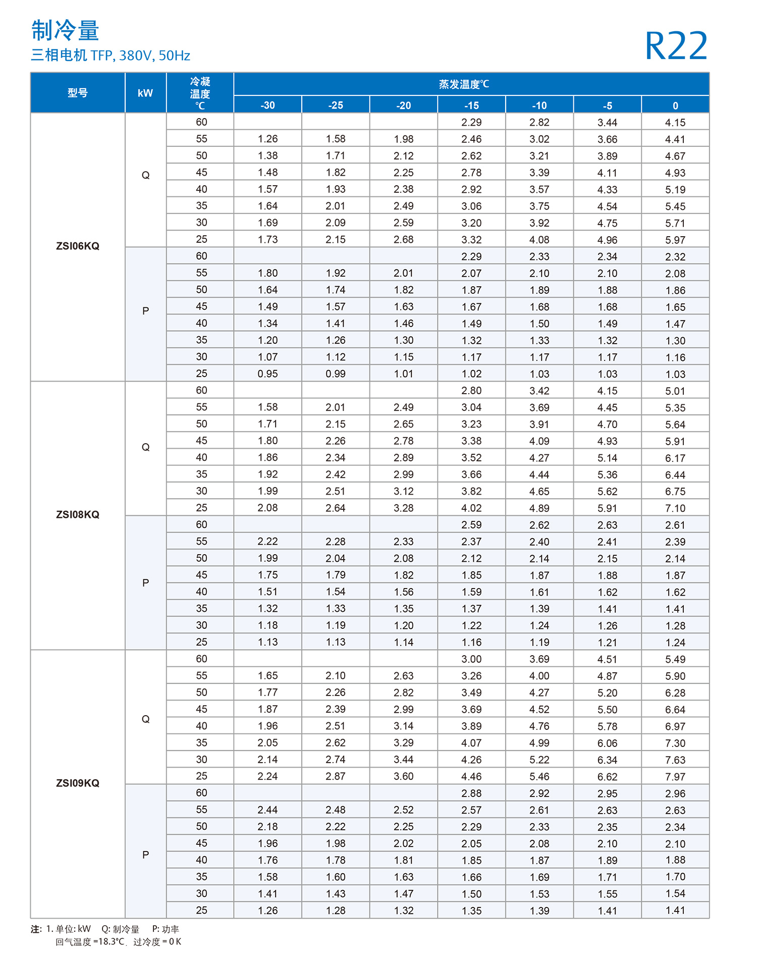
Under all application conditions, the return air temperature should be lower than 18.3 ℃, and the subcooling degree of the injection circuit should be greater than 1K.
Consult Emerson's local sales and applications engineer for any circumstances beyond the scope of an appeal.
Crankcase heater
For outdoor systems, if the system refrigerant charge exceeds the limits in Table 1, a crankcase heater is required for the compressor.
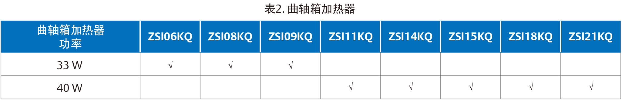
Table 2 contains a comparison of crankcase heaters and compressor models. If the customer purchases the crankcase heater separately from his own supplier,
Refer to Table 2 for crankcase heater power.
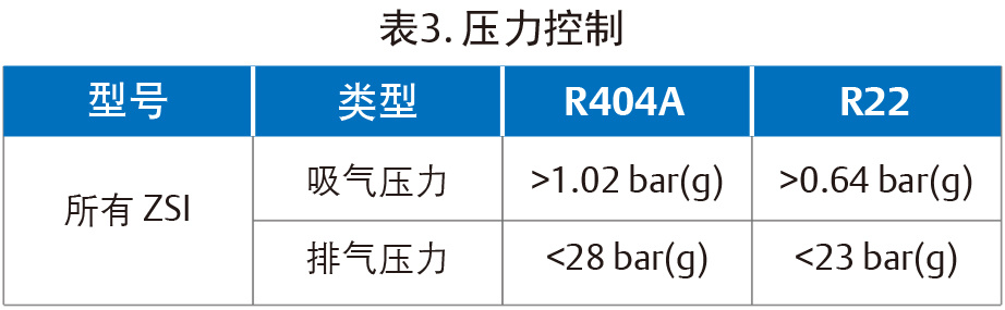
Pressure control
The system must be equipped with a pressure controller to achieve high and low pressure protection. The minimum/maximum pressure settings are given in Table 3.
Built-in pressure relief valve IPR
The ZSI compressor has a built-in pressure relief valve (IPR valve). When the pressure difference between exhaust and suction reaches 375 ~ 450psi, the IPR valve will open.
After a certain period of time, this action will cause the motor protector to disconnect, thereby stopping the compressor.
Motor protector
The motor protector type of ZSI series refrigeration compressor is built-in circuit breaker protector. In the model name, it is expressed as "F", for example: ZSI09KQE-TFP.
Parallel System Application
At present, all ZSI compressors are not allowed to be used in parallel. Consult Emerson's local sales and applications engineer for details.
Exhaust silencer
The gas flow of the scroll compressor is continuous, and accordingly, the exhaust pulse is low. For Copeland scroll compressors, there is no need to use the external exhaust pipe muffler often used in piston compressors. Due to differences in the system, the complete system manufacturer needs to perform separate tests to determine whether the system noise and vibration levels are acceptable.
Phase sequence of three-phase scroll compressor
Copeland scroll compressors can only compress in one direction of rotation. For single-phase compressors, the direction of operation is not a problem because they will always start and run in the correct direction. The direction of rotation of the three-phase compressor depends on the phase of the power supply, because there is a 50% chance that the power supply is connected to the opposite direction of rotation. It is very important that attention signs and instructions should be affixed to the appropriate position of the equipment to ensure that the system is installed and Operate in the correct direction. The method of judging whether the phase sequence is correct is whether the suction pressure will drop and the discharge pressure will rise when the compressor is energized. Compared with the pressure value of normal operation, there is no pressure difference during reverse rotation, and the compressor sometimes has abnormal noise.
The short (less than 1 hour) reverse rotation of the three-phase scroll compressor does not affect its life, but the lubricating oil may be lost. If the discharge tube is at least 6 inches (15cm) higher than the compressor head cover, you can avoid loss of lubricating oil when the compressor reverses. After the compressor reverses for a few minutes, the built-in protector will act to cut off the power supply of the compressor. If it is allowed to repeatedly restart and reverse operation without correction, the compressor will be permanently damaged.
The internal wiring of all three-phase scroll compressors is the same, so for a particular system or installation, as long as the correct phase is determined, the correct phase of the power supply can be connected to the corresponding end of the terminal to ensure the correct direction of rotation.
ZSI Single Phase Applications
Copeland cryogenic scroll ZSI06,ZSI08,ZSI11,ZSI14 four models can be applied to single-phase, rated voltage 220V, power supply frequency 50Hz, single-phase compressor can run in the rated voltage value of 10% range (198V ~ 242V).
Due to the inherent design characteristics of Copeland scroll compressor, its internal scroll always starts under unloading, so it has better low-voltage starting performance. Therefore, for the starting of ZSI single-phase compressor, other auxiliary starting components are usually not required, and PSC starting mode can meet the requirements. However, in special occasions such as high pressure difference, high ambient temperature or low voltage, CSR starting mode, auxiliary starting capacitors and relays are required, to increase the starting torque.
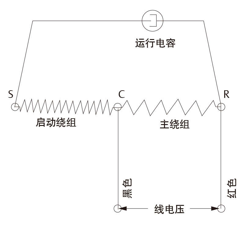
PSC启动:(Permanent Split Capacitor)
For some applications that do not require a high starting torque, a PSC starting method with only a running capacitor can meet the requirements. This starting method is also more economical and efficient, and is generally used in the working condition of system pressure balance during starting.
The PSC wiring requires a run capacitor. The start winding (C-S) of the motor forms a loop with the split capacitor, which is connected between the start winding (C-S) and the run winding (C-R), as shown in the figure.
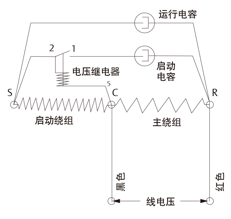
CSR启动:(Capacitor Star-Capacitor Run)
For some high pressure difference and large load application conditions, or the system pressure is not balanced before starting again, high ambient temperature, low voltage and other special occasions, need to consider the use of CSR start.
The CSR start mode has one more start capacitor and start relay than the PSC start mode. The starting relay is a normally closed design. When starting, the starting capacitor and the running capacitor are connected in parallel to generate a larger starting torque. After the compressor motor starts to reach the normal speed, there is enough voltage generated on the relay winding, which is the contact of the relay is closed, 1-2 is disconnected, so that the starting capacitor and the starting winding are disconnected.
High vacuum operation
Warning: Do not operate the Copeland scroll compressor under high vacuum conditions, otherwise it will cause electrical erosion and even burning of the compressor terminals and connectors, causing permanent damage to the compressor.
A low pressure controller or switch must be used to limit compressor vacuum operation. Refer to Table 3 in the Pressure Control section to set the low pressure controller.
Do not use scroll compressors (including all refrigerant type compressors) to vacuum the refrigeration or air conditioning system.
Refer to the Engineering Application Manual AE-1105 for proper vacuuming procedures.
"Withstand voltage" (AC high voltage) test
High voltage testing is usually done on the production line by the equipment manufacturer. High-voltage testing can also be done at the installation site, but usually field technicians do not have the corresponding test equipment.
The structure of the flexible scroll compressor is that the motor is in the lower part of the shell. Therefore, if there is refrigerant liquid in the shell, the scroll compressor motor is immersed in the refrigerant to a much greater extent than the hermetic piston compressor. The scroll compressor is then very similar to a semi-hermetic compressor, I .e. the horizontally placed motor part is immersed in oil and refrigerant. When the scroll compressor is subjected to a high voltage test, if there is a liquid refrigerant in the shell, the liquid refrigerant has a high conductivity relative to the refrigerant vapor and oil.
Therefore, the value of the leakage current will be larger than the compressor with the motor in the upper part. This phenomenon may occur in all compressors in which the motor is immersed in the refrigerant. This amount of leakage does not indicate any safety issue. In order to reduce the leakage current value, the system should run for a short time to make the refrigerant get a reasonable distribution, and then do the high voltage test again. Refer to the manual AE4-1294 resistance test. In any case, the compressor is not allowed to perform a high voltage test under vacuum.
Copeland Scroll Compressor Functional Inspection
The functional test of closing the suction valve of the compressor to check how low the suction can be reached does not indicate the performance of the compressor. This test can damage the scroll compressor. The following diagnostic methods can be used to determine whether a scroll compressor is functioning properly.
1. Check whether the power supply voltage of the unit is normal.
2. The regular inspection of the continuity of the motor winding and the short circuit to the ground shall be carried out to determine whether the built-in motor overload protector is tripped, whether the motor winding is short-circuited or short-circuited to the ground. If the motor protector trips, the compressor must cool down sufficiently to reset the protector.
3. Check whether the indoor and outdoor fans are operating normally.
4. Connect the pressure gauge on the suction and exhaust side, and connect the power supply of the compressor. If the inspiratory pressure is lower than normal, there may be a low charge or a blockage in the system.
5. If the suction pressure does not drop and the exhaust pressure does not rise to the normal value, replace the power connection of any two terminals of the compressor and then power on to confirm whether the compressor is running in the correct direction. If the pressure still does not reach the normal value, the reversing valve (if any) or the compressor may be damaged. Restore the wiring of the compressor to the original connection method, and check the quality of the reversing valve with the regular judgment method.
6. In order to test whether the compressor is discharging normally, the actual current consumed by the compressor must be compared with the current value at the same operating pressure and voltage in the published compressor performance curve. If the measured average current deviates from the published value by more than ± 15%, it may indicate that the compressor is damaged. A three-phase current imbalance of more than 15% of the average current may indicate a voltage imbalance and should be further investigated. More comprehensive compressor and system troubleshooting procedures can be found in Form 6400 in Chapter H of the Emerson Electrical Manual.
7. Before replacing or returning the compressor: It must be determined that the compressor is really damaged. At a minimum, the compressor returning from the site shall be subjected to a withstand voltage test in the workshop or warehouse, as well as a review of winding resistance and starting capacity before returning. During the warranty analysis of the compressors returned to Copeland, more than 1/3 of them were determined to be fault-free and were misdiagnosed as damaged at the site. Unnecessary replacement of a non-faulty compressor is a financial loss to all parties.
8. It is strictly forbidden to test the compressor by closing the suction valve or liquid pipe solenoid valve to vacuum the compressor.
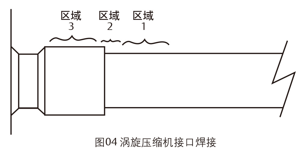
Initial installation
1. The suction, exhaust and injection pipes of the copper-plated steel of the scroll compressor can be welded like other copper pipes.
2. recommend welding materials-Any copper-silver alloy material can be used, preferably containing at least 5% silver. 0% silver content is still acceptable.
3. The recommend is blown with dry nitrogen to prevent carbonization on the inner surface of the pipe.
4. Ensure that the inner diameter of the joint pipe and the outer diameter of the pipe are clean before installation.
5. Heat Zone 1. After the tube temperature reaches the welding temperature, move the torch flame to zone 2. (See Figure 04)
6. Heat zone 2 until the welding temperature is reached, move the welding gun up and down, and rotate around the pipe if necessary to heat the pipe evenly. Add solder to the welding head while rotating the welding gun around the joint.
7. After the solder flows all around the joint, move the torch to zone 3 for heating. This allows solder to enter the joint. Access to Zone 3 should be minimal.
8. For any welded joint, excessive heating results will have an adverse effect.
Field Service
1. Disconnection: Recover the refrigerant from the high and low pressure sides of the system at the same time, and cut the pipe near the compressor.
2. Re-connection: recommend solder material used: copper-silver alloy containing at least 5% silver or silver solder with flux.
3. Insert the tube into the joint.
4. Heat the tube evenly in zone 1 and move slowly to zone 2. When the joint reaches the soldering temperature, the solder is applied.
5. Heat evenly around the joint to fully fill the joint with solder.
6. Slowly move the gun to Zone 3 to get the solder into the joint.
Do not overheat the weld.
Warning
If the refrigerant in the system is discharged only from the high pressure side, it may sometimes be because the seal of the scroll prevents system pressure equalization through the compressor. Thus there is still pressure in the compressor housing and in the low-pressure line. If the welding gun is applied to the low pressure side at this time, the pressurized refrigerant and oil mixture will escape and ignite in contact with the flame. It is important to check the pressure on the high and low pressure sides with the pressure gauge set before welding or when repairing the unit on the assembly line, and to release the refrigerant from the high and low pressure sides at the same time. This instruction should be clearly stated on the corresponding product documents or in the assembly (overhaul) area.
Compressor replacement after motor burn-out
When the motor burns out, most of the contaminated oil will be replaced with the damaged compressor. The rest of the oil can be cleaned by using the dry filter of the suction line and the liquid line. It is recommend to use 100% active aluminum suction dry filter, but it must be removed after 72 hours. Refer to Application Engineering Manual 24-1105 for cleaning procedures, and Application Engineering Manual 11-1297 for recommendations for liquid line dry filters.
Attention! If there is a gas-liquid separator in the system, it is strongly recommended to replace it. This is because the oil return hole or filter screen in the gas-liquid separator may be blocked by debris or become blocked within a short time after the compressor is damaged. This will cause a second damage to the replacement compressor due to lack of oil.
System filling procedure
The system should be filled with liquid from the high-pressure side to maximize the amount of charge as much as possible, which can prevent the compressor from running under insufficient refrigerant conditions. Sufficient suction can not only cool the motor, but also effectively prevent poor lubrication caused by excessive exhaust temperature.
Most of the charge should be placed on the high-voltage side of the system to prevent low-voltage start-up difficulties caused by high loads at the first start-up. If additional refrigerant needs to be added, run the compressor and fill the low pressure side with fluid. Both high-pressure side pre-charging and low-pressure side liquid filling in the system are performed to prevent the compressor from operating at abnormally low suction pressure during refrigerant charging.
Note:Do not use the compressor to test the cut-off point of the high-voltage switch. Bearings are susceptible to damage due to high loads before running in without a few hours of normal operation.

recommend products
Get free product quotes

Mobile website
More wonderful waiting for you!
Address: No. 330-3, Dingxiang Street, Sujiatun District, Shenyang City, Liaoning Province
Mobile:15841552555(WeChat synchronization)
E-mail:northsnow_trade@outlook.com